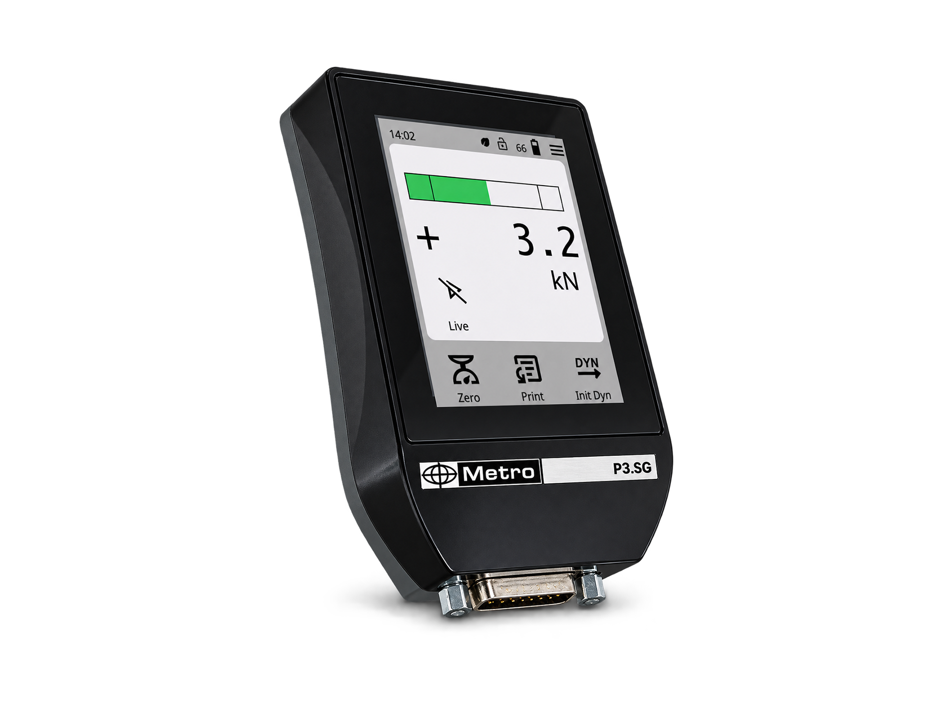
F1 / F2 / F3 Displays for Strain Gauge sensors
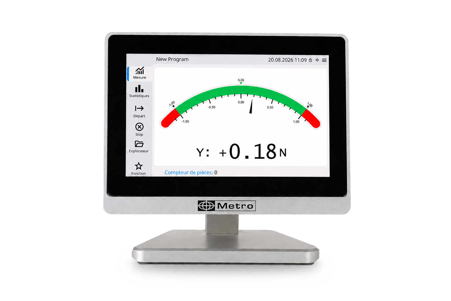
Industrial displays for strain gauge sensors
The F1, F2, and F3 displays feature a 5-inch capacitive touchscreen, with an accuracy of 0.01% of full scale and a sampling rate of 4,800 Hz. TEDS-compatible, they automatically recognize plug-and-play strain gauge sensors, for measuring force, weight, torque, or pressure.
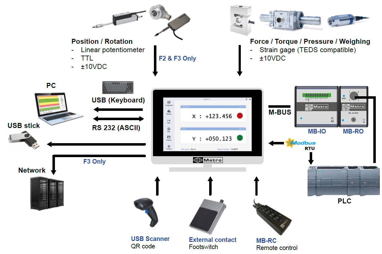
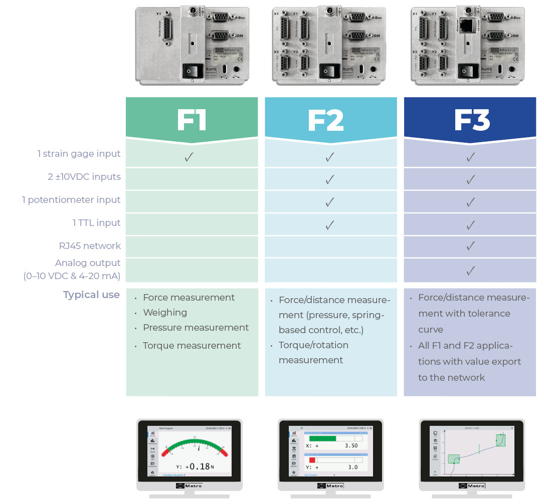
The F1 is the base version for force measurement. The F2 adds distance measurement (potentiometer, TTL, or ±10VDC), for applications combining force and displacement. The F3 completes the range with an analog output, Ethernet connectivity, an SD card for measurement storage, and tolerance curve display. All three versions are compatible with M-Bus modules (MB-IO, MB-RO) for easy integration into automated systems.
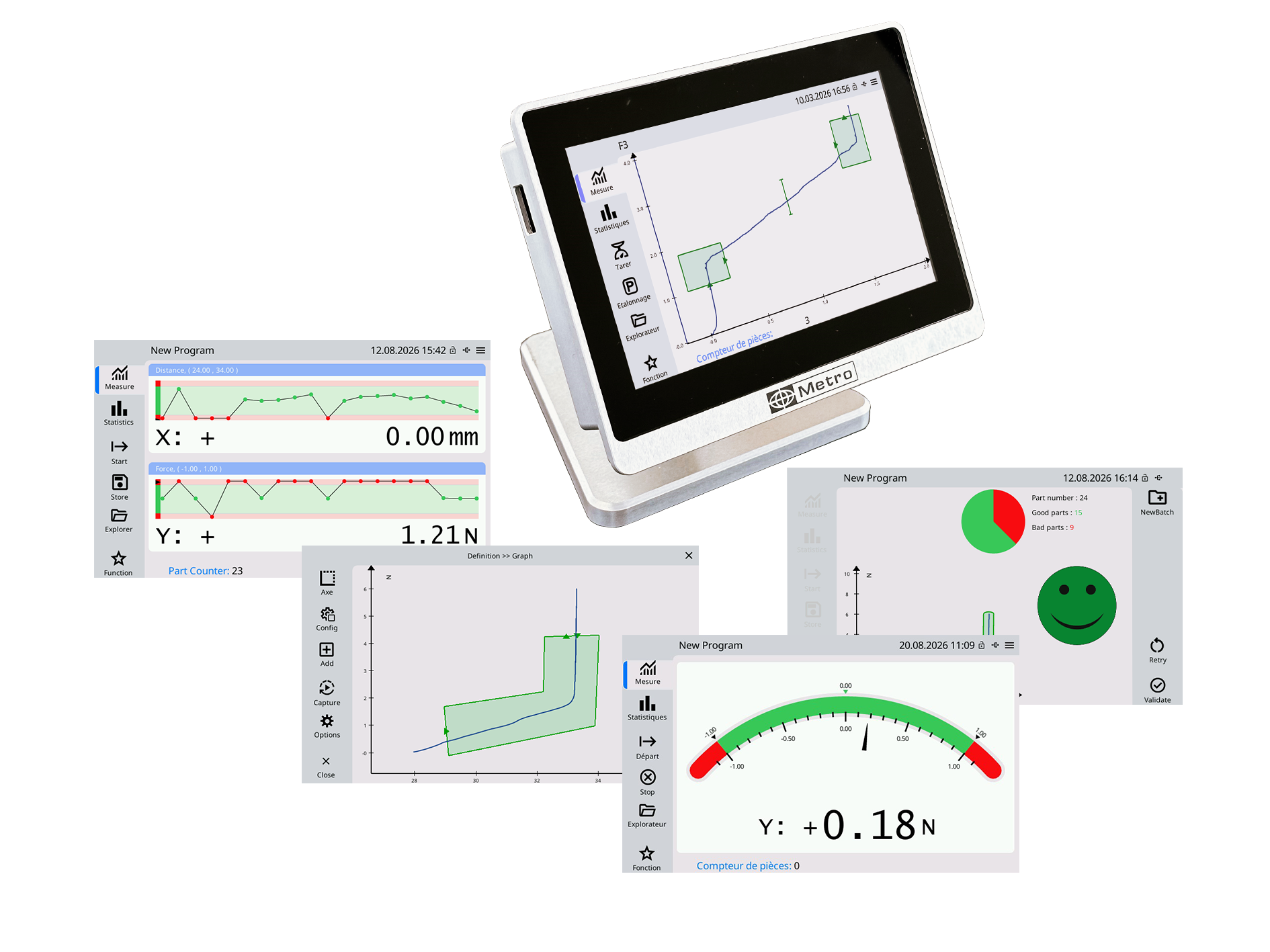
The F1, F2 and F3 are equipped with a 12.7 cm (5 inch) capacitive color touch screen with a resolution of 800*480px. Its highly intuitive user interface allows for quick programming and easy handling by any operator.
The measurements can be displayed in the form of bar graphs, smileys, numerical values only and even visualize the history of the measurements in real time in the form of a graph.
A sequence editor allows total control of the display and the progress of the measurement.
Metro displays offer several data transfer solutions:
- A USB-C (device) port allows for very simple data transfer without the need to install a driver.
- A COM port (SUBD-9) allows for communication with an ASCII and Modbus RTU protocol for PLCs.
Only on F2 and F3:
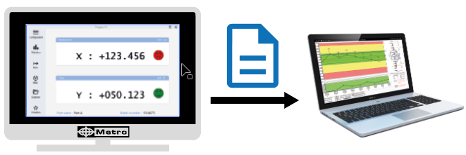
A USB-A port (Host) allows you to create CSV files on a USB stick, but also to connect a QR code reader.
Only on the F3:
An Ethernet port allows you to generate files on your network using the MetroDataServer software, but also to communicate with a PLC in Modbus TCP.

TEDS (Transducer Electronic Data Sheet) is a technology that stores sensor-specific information such as calibration data and model details. When connected to the display, the sensor is automatically recognized and configured, eliminating the need for manual configuration.
Main advantages:
- Plug & Play – Fast and error-free sensor installation
- Improved accuracy – Integrated calibration guarantees precise measurements
- Simplified management – No need for external documentation or manual entry of parameters
Metro displays are compatible with TEDS 0 and 1-wire. If your sensor is not equipped with a TEDS chip, you can enter the information manually (sensitivity, etc.).
General characteristics
|
Display model |
F1 |
F2 |
F3 |
|
Screen size |
5’’ (12.7cm) - Capacitive with 800*480px resolution |
||
|
Adjustable stand |
Yes |
||
|
Panel mounting bracket |
In option |
||
|
Programmable buzzer |
Yes |
||
|
Force units |
N, kN, lbf, daN, Kgf |
||
|
Distance unit |
mm, µm, inch, mil |
||
|
Weighing units |
g, kg, t, mg, lb, oz |
||
|
Torque units |
N.m, lbf.ft, lbf.in, |
||
|
Pressure unit |
Pa, kPa, bar, mbar, atm, mmHg, inHg, psi |
||
|
Number of programs in memory |
1 |
6 |
20 |
|
Display and evaluation of measurements |
- Digital values |
- Digital values |
- Digital values |
|
Timestamping of measurements |
- |
Yes |
|
|
Password protection |
Yes |
||
|
Measurement sequence |
Yes |
||
|
Simple statistics |
- |
Yes |
|
Connectors
|
Display model |
F1 |
F2 |
F3 |
|
Force measurement |
4 or 6-wire strain gauge |
||
|
Force connector 1 |
SUBD-15 (HBK Pinout) |
||
|
TEDS Force 1 |
Yes |
||
|
Force connector 2 |
- |
SUBD-9 (±10VDC) |
|
|
Distance measurement |
- |
Potentiometer, TTL or ±10VDC |
|
|
Distance connector 1 |
- |
SUBD-15 (Potentiometer or ±10VDC) |
|
|
Distance connector 2 |
- |
SUBD-15 (TTL - Heidenhain Pinout) |
|
|
Power supply |
24VDC |
||
|
Power connector |
Jack Lockable 760K Switchcraft |
||
|
M-BUS extension |
Yes, SUBD-9 Female |
||
|
Optocoupled inputs/outputs |
Max 32 via external M-Bus module (MB-IO) - each module has 8 I/O |
||
|
RS232 connector |
SUB-9 Female with |
||
|
USB-A connector |
- |
- USB flash drive (export CSV file, export configuration) |
|
|
RJ45 connector |
- |
- |
Yes, with |
|
External contact input |
Jack 3,5mm |
||
|
USB-C connector |
Yes for data output, USB keyboard emulation type |
||
|
SD card |
- |
Yes for storing measurements |
|
Measurement performance
|
Display model |
F1 |
F2 |
F3 |
|
Force measurement accuracy (strain gauge) |
0.01% of full scale (display only) |
||
|
Resolution of force measurement (strain gauge) |
measurement range / 10,000 |
||
|
Strength measurement sampling rate (strain gauge) |
5kHz |
||
|
Distance Measurement (TTL) Accuracy |
N/A |
up to ±0.2µm over the course (depending on the sensor) |
|
|
Distance Measurement (TTL) Resolution |
N/A |
up to 0.0001 mm (depending on the sensor) |
|

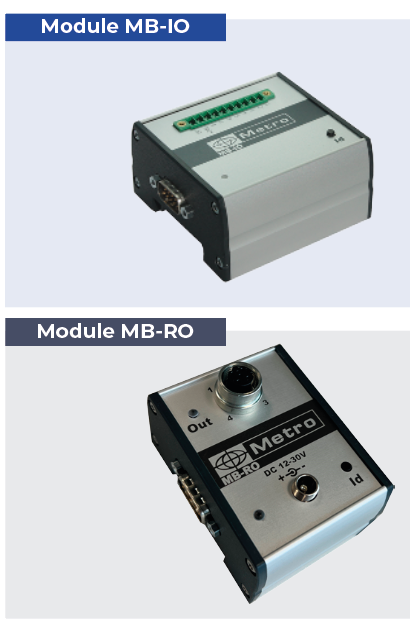
These 2 modules are usually installed in an electrical cabinet on a DIN rail. Thanks to its 8 inputs/outputs isolated by optocouplers,
the MB-IO module allows the interfacing of automation components to F1/F2/F3. Up to 4 MB-IOs, i.e. 32 inputs/outputs, can be managed.
Each terminal is equipped with 2 optocouplers and can be easily configured as an input or output from the touch interface.
Simply select a terminal and assign it a function from the thirty or so available, for example:
- Good / bad part
- Data transfer
- Cycle start
- etc.
The operation is very flexible, allowing, for example, a light to flash during the control, or a siren to sound if a force threshold is exceeded.
The MB-RO has a relay output with the same programmable function principle.
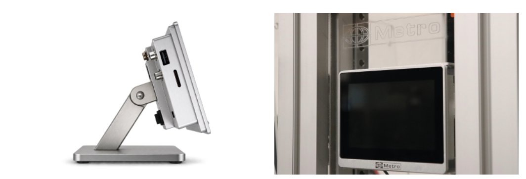
The F1-F2-F3 can be supplied with an orientable stand or can be integrated into a panel. The M-BUS modules are mounted on a DIN rail
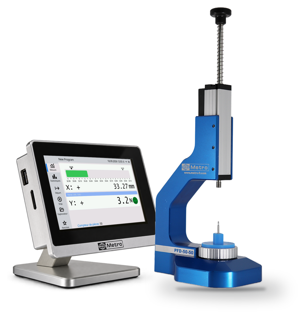
Miniature benchpress for watchmaking applications.
These Miniature benchpress enable force and displacement (optional) to be monitored during watch component assembly operations. A force sensor is integrated into the base and a potentiometric displacement sensor acts as a vertical axis. The display allows the quality of the assemblies to be monitored.
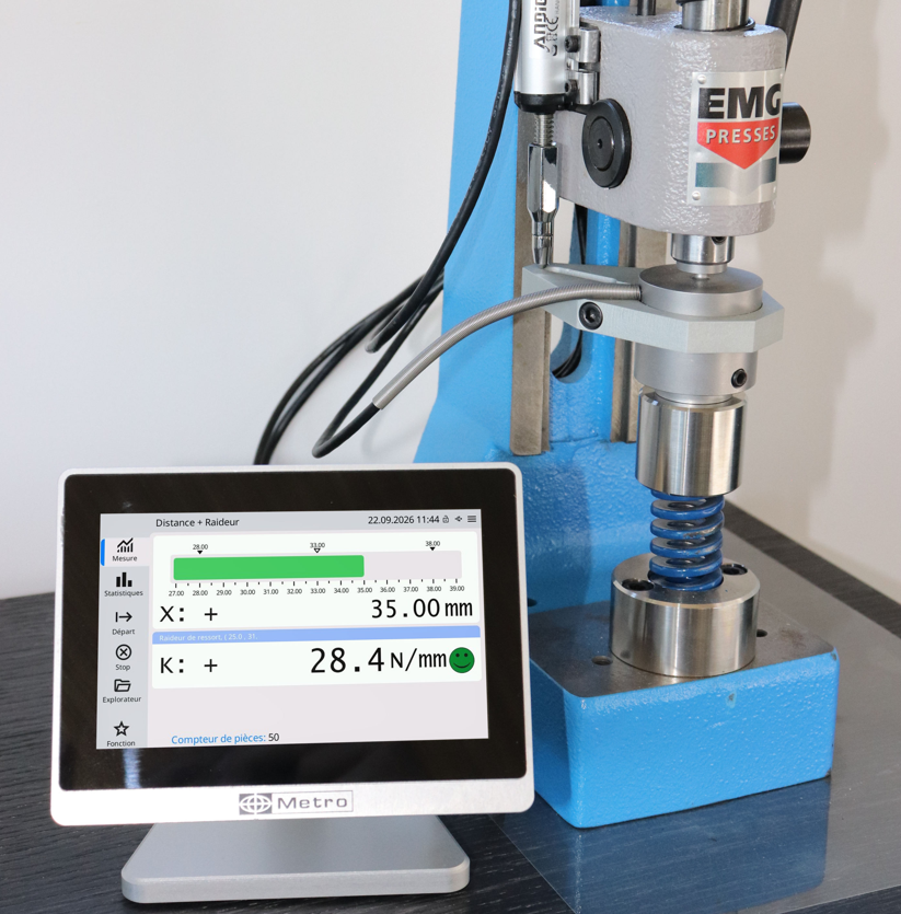
<p style="text-align: justify;"><strong><em>Testing springs and elastic components.</em></strong></p>
<p style="text-align: justify;"><em>A spring is not checked on dimensions but on the <strong>force it develops at a given length</strong>. The <strong>F3</strong> display acquires force and displacement simultaneously, so the load is recorded at exactly the required position and the rate can be calculated between two lengths. Sorting becomes <strong>objective and repeatable</strong>, at the workstation rather than in the laboratory.</em></p>

Integration into automated machinery.
On a high-rate assembly machine, the verdict has to reach the PLC without operator involvement. The F3 display offers an analogue output and Ethernet connectivity, and all three versions work with the MB-RO M-Bus module to trigger an ejection or a cycle stop. Non-conforming parts are removed before the next station.
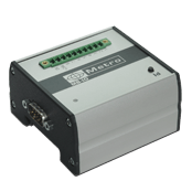
The MB-IO M-Bus box has 8 optocoupled inputs/outputs for additional functionality, e.g. output of good or bad parts, calibration input etc. The M-Bus units are presented in an aluminum profile that can be mounted on a standard DIN rail. More details on this page: M-BUS
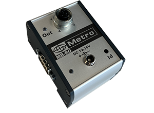
Module with one relay output - to pilot air economy system or air gage probe output.
It is fitted with a M12 connector
To be used with the cable 45186-1.5
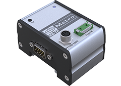
The MB-TP module is used to read a type K thermocouple or a PT100 probe and use it on a Metro display to create an alarm on a temperature variation or to perform temperature compensation of the measurement.
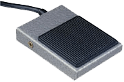
This sturdy pedal can be configured in different ways: calibration, measurement transmission, start of dynamic measurement etc...
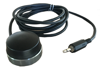
This robust and ergonomic button is made on a machined aluminum base.
It advantageously replaces the pedal when it is used on a table.
Compatible with all Metro products: Displays and multiplexers.
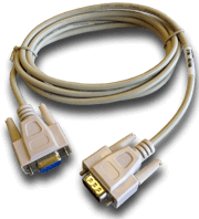
This cable is used to connect the M2/M3 to a computer.
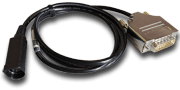
This adapter cable allows to connect 1 Magnescale sensor (Sony) on TTL display unit. The SUBD-15 connector contains an electronic card which manages the error signal of a Magnescale sensor.
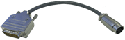
This cable allows to connect 1 Mitutoyo sensor on a TTL display.